
RDAS Weather Radar Signal Processor and Control System
Radar signal processing and control solutions for weather radar modernization and operational use.
Overview
Radar signal processing and control solutions for weather radar modernization and operational use.
RDAS2000B Rev 1.0Introduction:
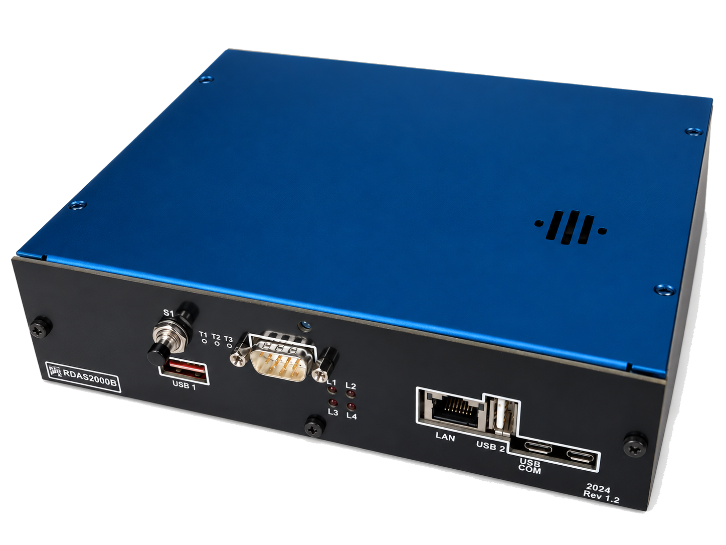
RDAS2000B (RDAS) is a stand alone modular Radar Data Acquisition and Control System based on the Red Pitaya Linux CPU board ( RP )
for Video signal processing and a separate board for antenna control based on the STM32F4 ARM M4 MCU.
RDAS is capable of digitising 14 bit Log Video signals at 50 MHz per channel. RDAS is also capable of controlling and monitoring various
user defined parameters on the radar and the antenna servo system.
RDAS communicates with a host processor via TCP/IP on a Gigabit Ethernet LAN.
The system time and date are kept by Real Time Clock (RTC) chip and GPS data.
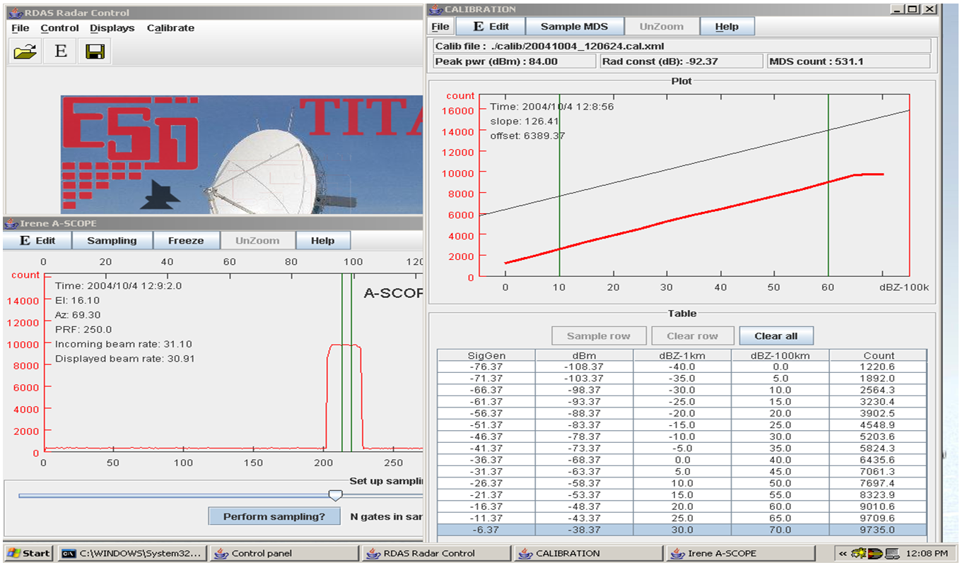
This system has been specially designed to work with TITAN running on a Linux machine and the RdasControl JAVA based calibration and
control utilities that can run under Linux and Win XP/7/10.
RDAS is currently a high resolution non Doppler system.
The heart of the RDAS card is the Red Pitaya ( RP ) CPU board that runs a scaled version of Debian Linux.
The sample rate process is started on the rising edge of the trigger.
RDAS digitises the Log Video signal at a sample rate determined by the user set-up ( Gate Size ).
The unprocessed 14 bit range samples are stored in a “raw range” buffer for processing.
Once the pre determined number of range buffers have been accumulated and processed the DSP processes raw sample buffers to produce a Beam of processed data.
These data are passed into the Beam Data Format buffer that also contains other header information such as the time , date, azimuth, elevation etc.
The Beam of processed data is then sent via Ethernet TCP/IP the host computer.
RDAS also listens on the TCP/IP port for incoming commands from the host computer. Each command is checked for validity and then sent to the command handler.
Common commands are the switching of Radar units ON or OFF, setting of number of range gates and controlling of the Antenna .
RDAS updates the Azimuth and Elevation position and status/control on each beam sent to the host machine.
RDAS can run in several operating modes specified by the user through the RdasControl program.
In Volume scan mode the system will run continuously producing beam data without any further commands or user intervention.
In Volume Scan mode RDAS does not send any beam data to TITAN while the antenna is slewing between elevation steps.
If the Ethernet connection is unplugged or the connection is broken while RDAS is busy sending beam data to TITAN RDAS will shut down the radar
and go into standby waiting for the connection to be re-established.
Communication between the RP board and the Antenna Control board is achieved through UART @115200 Baud.
The Antenna Control board receives commands from the Host Computer via the RP Board.
The RP receives commands from RdasControl via Ethernet and then parses the commands into an ASCII command format to send to the Antenna Control Board ( ACB )via TTL UART.
The ACB has the capability of acquiring antenna position via Parallel interface or via Synchro to Digital Converter board. The SDCB plugs into the ACB.
The ACB controls the antenna motors movement with Digital To Analog ( DAC ) signals, one for Azimuth and One for Elevation. The DAC is internal on the STM32 MCU chip on the ACB.
A GPS module that is plugged into the ACB is used for accurate date and time keeping.
The firmware on the ACB is updatable via USB flash drive in the form of a binary file.
The ACB also has several communication ports for debug and monitoring of system status and communication with external units such as the
Radar Control Unit ( RCU ) which is a separate box used for switching ON and OFF and monitoring of radar systems and status.
For more information about this product, please contact ESD International.
← Back to all products